- 您现在的位置:买卖IC网 > Sheet目录450 > ISL5216EVAL1 (Intersil)EVALUATION BOARD FOR ISL5216KI
�� �
�
�ISL5216�
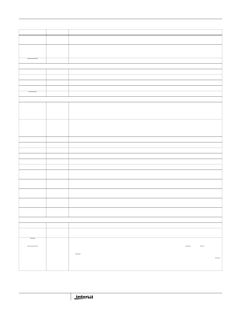
�Pin� Descriptions�
�(Continued)�
�NAME�
�SYNCI3�
�SYNCO�
�RESET�
�JTAG�
�TDO�
�TDI�
�TMS�
�TCLK�
�TRST�
�OUTPUTS�
�SD1A�
�SD2A�
�SD1B�
�SD2B�
�SD1C�
�SD2C�
�SD1D�
�SD2D�
�SCLK�
�SYNCA�
�SYNCB�
�SYNCC�
�SYNCD�
�TYPE�
�I�
�O�
�I�
�O�
�I�
�I�
�I�
�I�
�O�
�O�
�O�
�O�
�O�
�O�
�O�
�O�
�O�
�O�
�O�
�O�
�O�
�DESCRIPTION�
�Synchronization� input� signal� for� channel� 3.� Same� functions� as� SYNCI� but� connects� only� to� channel� 3.� This� pin�
�is� internally� pulled� low� to� allow� it� to� be� left� unconnected.�
�Synchronization� Output� Signal.� The� processing� of� multiple� ISL5216� or� HSP50216� devices� can� be�
�synchronized� by� tying� the� SYNCO� from� one� ISL5216� device� (the� master)� to� the� SYNCI� of� all� the�
�ISL5216/HSP50216� devices� (the� master� and� slaves).�
�Reset� Signal.� Active� low.� Asserting� reset� will� halt� all� processing� and� set� certain� registers� to� default� values.�
�Test� data� out�
�Test� data� in.� Contains� weak� internal� pull-up.�
�Test� mode� select.� Contains� weak� internal� pull-up.�
�Test� clock.� Contains� weak� internal� pull-down.�
�Test� reset.� Active� low.� Contains� weak� internal� pull-down.�
�Serial� Data� Output� 1A.� A� serial� data� stream� output� which� can� be� programmed� to� consist� of� I1,� Q1,� I2,� Q2,�
�magnitude,� phase,� frequency� (d� φ� /dt),� AGC� gain,� and/or� zeros.� In� addition,� data� outputs� from� Channels� 0,� 1,� 2�
�and� 3� can� be� multiplexed� into� a� common� serial� output� data� stream.� Information� can� be� sequenced� in� a�
�programmable� order.� See� Serial� Data� Output� Formatter� Section� and� Microprocessor� Interface� Section.�
�Serial� Data� Output� 2A.� This� output� is� provided� as� an� auxiliary� output� for� Serial� Data� Output� 1A� to� route� data� to�
�a� second� destination� or� to� output� two� words� at� a� time� for� higher� sample� rates.� SD2A� has� the� same�
�programmability� as� SD1A� except� that� floating� point� format� is� not� available.� See� Serial� Data� Output� Formatter�
�Section� and� Microprocessor� Interface� Section.�
�Serial� Data� Output� 1B.� See� description� for� SD1A.�
�Serial� Data� Output� 2B.� See� description� for� SD2A.�
�Serial� Data� Output� 1C.� See� description� for� SD1A.�
�Serial� Data� Output� 2C.� See� description� for� SD2A.�
�Serial� Data� Output� 1D.� See� description� for� SD1A.�
�Serial� Data� Output� 2D.� See� description� for� SD2A.�
�Serial� Output� Clock.� Can� be� programmed� to� be� at� 1,� 1/2,� 1/4,� 1/8,� or� 1/16� times� the� clock� frequency.� The�
�polarity� of� SCLK� is� programmable.�
�Serial� Data� Output� 1A� sync� signal.� This� signal� is� used� to� indicate� the� start� of� a� data� word� and/or� frame� of� data.�
�The� polarity� and� position� of� SYNCA� is� programmable.�
�Serial� Data� Output� 1B� sync� signal.� This� signal� is� used� to� indicate� the� start� of� a� data� word� and/or� frame� of� data.�
�The� polarity� and� position� of� SYNCB� is� programmable.�
�Serial� Data� Output� 1C� sync� signal.� This� signal� is� used� to� indicate� the� start� of� a� data� word� and/or� frame� of� data.�
�The� polarity� and� position� of� SYNCC� is� programmable.�
�Serial� Data� Output� 1D� sync� signal.� This� signal� is� used� to� indicate� the� start� of� a� data� word� and/or� frame� of� data.�
�The� polarity� and� position� of� SYNCD� is� programmable.�
�MICROPROCESSOR� INTERFACE�
�P(15:0)�
�ADD(2:0)�
�WR�
�or�
�DSTRB�
�I/O�
�I�
�I�
�5�
�Microprocessor� Interface� Data� bus.� See� Microprocessor� Interface� Section� .� P15� is� the� MSB.�
�Microprocessor� Interface� Address� bus.� ADD2� is� the� MSB.� See� Microprocessor� Interface� Section� .� Note:� ADD2�
�is� not� used� but� designated� for� future� expansion.�
�Microprocessor� Interface� Write� or� Data� Strobe� Signal.� When� the� Microprocessor� Interface� Mode� Control,� μ� P�
�MODE,� is� a� low� data� transfers� (from� either� P(15:0)� to� the� internal� write� holding� register� or� from� the� internal� write�
�holding� register� to� the� target� register� specified)� occur� on� the� low� to� high� transition� of� WR� when� CE� is� asserted�
�(low).� When� the� μ� P� MODE� control� is� high� this� input� functions� as� a� data� read/write� strobe.� In� this� mode� with�
�RD/WR� low� data� transfers� (from� either� P(15:0)� to� the� internal� write� holding� register� or� from� the� internal� write�
�holding� register� to� the� target� register� specified)� occur� on� the� low� to� high� transition� of� Data� Strobe.� With� RD/WR�
�high� the� data� from� the� address� specified� is� placed� on� P(15:0)� when� Data� Strobe� is� low.� See� Microprocessor�
�Interface� Section� .�
�FN6013.3�
�July� 13,� 2007�
�发布紧急采购,3分钟左右您将得到回复。
相关PDF资料
ISL5217EVAL1
EVALUATION BOARD FOR ISL5217KI
ISL5239EVAL1
EVALUATION BOARD FOR ISL5239
ISL5239KIZ
IC LINEARIZER PRE-DISTORT 196BGA
ISL5416EVAL1
EVALUATION PLATFORM FOR ISL5416
ISL55005IEZ-T7
IC AMP MMIC BIPO BROADBND SC70-6
ISL55007IEZ-T7
IC AMP MMIC BIPO BROADBND SC70-6
ISL55008IEZ-T7
IC AMP MMIC BIPO BROADBND SC70-6
ISL55009IEZ-T7
IC AMP MMIC BIPO BROADBND SC70-6
相关代理商/技术参数
ISL5216KI
功能描述:上下转换器 QUAD DIGITAL DOWNCONVERTER,IND TEMP,0.8M RoHS:否 制造商:Texas Instruments 产品:Down Converters 射频:52 MHz to 78 MHz 中频:300 MHz LO频率: 功率增益: P1dB: 工作电源电压:1.8 V, 3.3 V 工作电源电流:120 mA 最大功率耗散:1 W 最大工作温度:+ 85 C 安装风格:SMD/SMT 封装 / 箱体:PQFP-128
ISL5216KI-1
功能描述:上下转换器 QUAD DIGITAL DOWNCONVERTER,IND TEMP,1.OMM PITCH BGA PACKAG RoHS:否 制造商:Texas Instruments 产品:Down Converters 射频:52 MHz to 78 MHz 中频:300 MHz LO频率: 功率增益: P1dB: 工作电源电压:1.8 V, 3.3 V 工作电源电流:120 mA 最大功率耗散:1 W 最大工作温度:+ 85 C 安装风格:SMD/SMT 封装 / 箱体:PQFP-128
ISL5216KI-1Z
功能描述:上下转换器 W/ANL QD DIG DWNCNVRTR 1 OM PITCH RoHS:否 制造商:Texas Instruments 产品:Down Converters 射频:52 MHz to 78 MHz 中频:300 MHz LO频率: 功率增益: P1dB: 工作电源电压:1.8 V, 3.3 V 工作电源电流:120 mA 最大功率耗散:1 W 最大工作温度:+ 85 C 安装风格:SMD/SMT 封装 / 箱体:PQFP-128
ISL5216KIZ
功能描述:上下转换器 W/ANNEAL QD DIGTL DWNCNVRTR IND TEMP RoHS:否 制造商:Texas Instruments 产品:Down Converters 射频:52 MHz to 78 MHz 中频:300 MHz LO频率: 功率增益: P1dB: 工作电源电压:1.8 V, 3.3 V 工作电源电流:120 mA 最大功率耗散:1 W 最大工作温度:+ 85 C 安装风格:SMD/SMT 封装 / 箱体:PQFP-128
ISL5217
制造商:INTERSIL 制造商全称:Intersil Corporation 功能描述:Quad Programmable Up Converter
ISL5217_05
制造商:INTERSIL 制造商全称:Intersil Corporation 功能描述:Quad Programmable Up Converter
ISL5217EVAL1
功能描述:EVALUATION BOARD FOR ISL5217KI RoHS:是 类别:RF/IF 和 RFID >> RF 评估和开发套件,板 系列:- 标准包装:1 系列:- 类型:GPS 接收器 频率:1575MHz 适用于相关产品:- 已供物品:模块 其它名称:SER3796
ISL5217KI
功能描述:上下转换器 196BGA,-40+85C PROGRAMMABLE QUAD UP CONVERTER RoHS:否 制造商:Texas Instruments 产品:Down Converters 射频:52 MHz to 78 MHz 中频:300 MHz LO频率: 功率增益: P1dB: 工作电源电压:1.8 V, 3.3 V 工作电源电流:120 mA 最大功率耗散:1 W 最大工作温度:+ 85 C 安装风格:SMD/SMT 封装 / 箱体:PQFP-128